
InOne is a Hexatronic infrastructure system that delivers DC power and optical fiber to distributed field devices (IoT sensors, CCTV cameras, 5G small cells and similar) through one hybrid micro cable. This article explains the engineering problem it addresses, the design decisions behind it, its components and behavior, and its effect on project cost.
Audience: customers, consultants and system integrators. Product information: hexatronic.com/en/powered-fiber. Design tool: inone-design.com.
Summary- Distributed field devices draw tens of watts each and sit hundreds of meters to several kilometers from the power source. 230 V AC installation rules were written for the opposite case: kilowatt loads over short distances.
- Over long distances, the AC cable cross-section is set by the 0.4 s fault-disconnection requirement and the voltage-drop limit, not by the load. For a 200 W load, the practical minimum AC conductor is about 6 mm² at 500 m, 16 mm² at 1 km and 95 mm² at 5 km.
- InOne removes these two constraints: it uses 110 V DC (extra-low voltage), electronic fuses instead of miniature circuit breakers, and a design limit of 50% voltage drop with regulation at every node. Power and fiber run in one hybrid micro cable of 6–12 mm outer diameter.
- The system has three parts: the HDN (rectifier, hybrid ODF, electronic fuses), the hybrid micro cable, and the HAN (fiber termination, voltage regulation to 48/53 V DC, industrial switch with PoE).
- Supported topologies are point-to-point, daisy chain, tree/fan-out and ring. The ring provides redundancy against a single cable cut. Physical-layer sensors (voltage, current, door, tamper, temperature, humidity) report to NMS, PSIM or VMS over SNMP or Modbus over IP.
- Smaller cable and less civil work lower the infrastructure share of the budget. The customer can keep the saving, reinvest it in the application, or combine both.
InOne is a hybrid power and fiber infrastructure system. A single hybrid cable carries copper conductors for DC power and optical fibers for communication, so one installation delivers both power and data to devices in the field.
InOne is infrastructure, not an application. It is the common foundation that applications run on, for example:
- IoT sensors and gateways
- CCTV and video surveillance, including radars and other perimeter sensors
- 5G small cells and microcells
- Other edge devices that need both power and connectivity
Because power and fiber arrive in one cable, there is no separate power cable, no separate fiber cable and no local mains connection at each device location. In practice this means lower cost (less civil work, one cable instead of two), faster deployment, and in many countries no licensed electrician for the DC network. The effect is largest for devices on streetlight poles, building façades and other remote or outdoor locations.
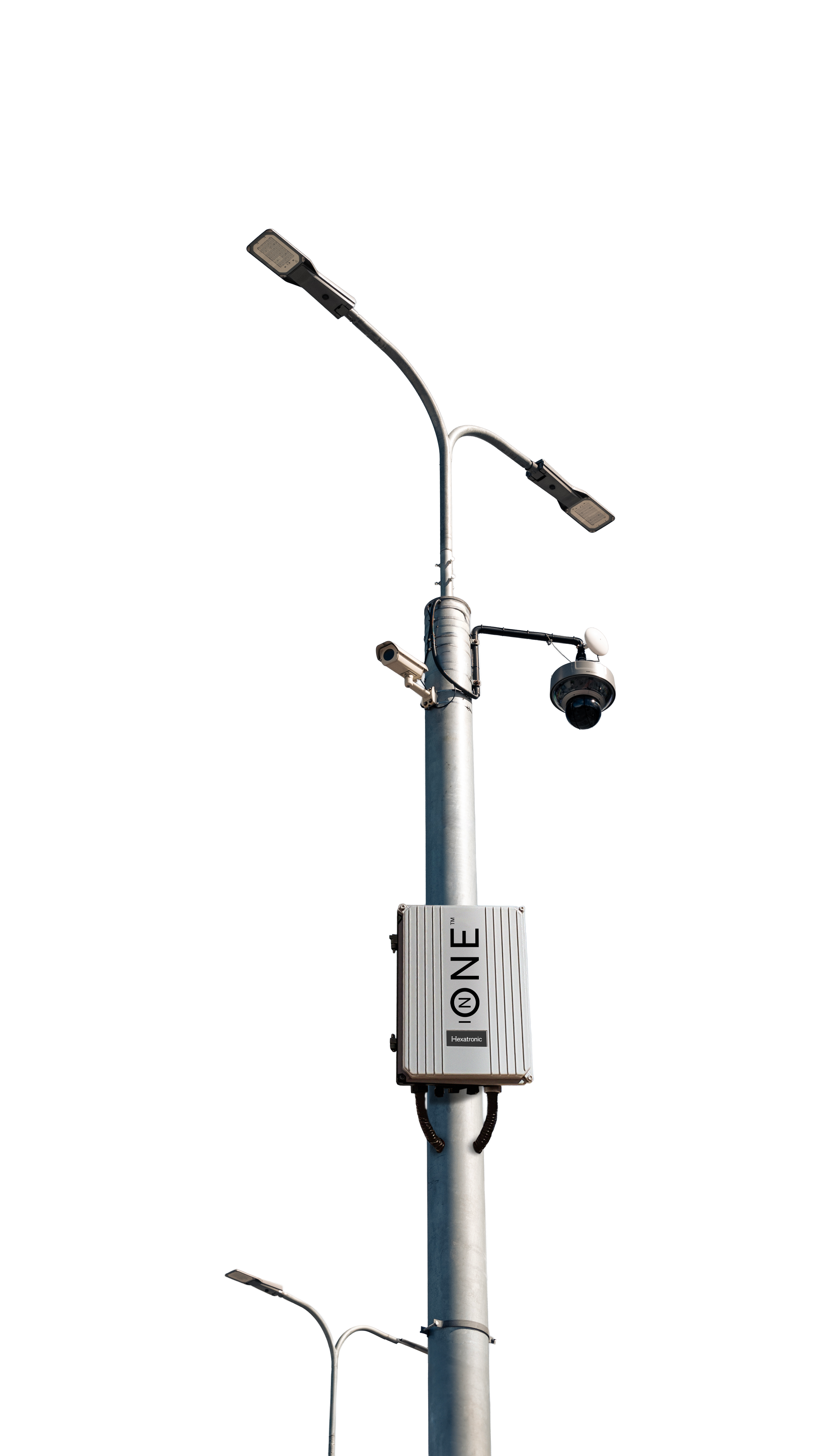
The core problem InOne addresses is the dimensioning of AC power cables. In a conventional design, field devices are fed from 230 V AC. The conductor cross-section is set by:
- electrical physics: current, resistance, voltage drop and losses over distance;
- national installation rules, which differ in detail between countries but follow the same international principles;
- safety requirements, in particular protection against electric shock and fire.
The problem is most severe in networks with low loads spread over long distances, which is the normal case for IoT, CCTV and small-cell networks. Each device needs little power, but the AC rules still require a large conductor because of the distance. The cable ends up oversized for the load it carries.
Most other project problems follow from the cable size. A smaller cable is faster to deploy, costs less in copper, transport, ducts and civil work, and makes redundancy and later extensions easier to build.
3. Application profile: IoT/CCTV networks versus standard AC networksIoT and CCTV networks have the opposite power profile from the installations that AC standards were written for.
IoT/CCTV networks: low load per node, long distances.
- Typical fixed CCTV camera: 20–30 W.
- PTZ (pan-tilt-zoom) camera: about 60 W, up to about 90 W.
- Distance from the power source: from about 100 m up to several kilometers.
Standard AC installations: high load, short distances.
- A home or business draws tens of kilowatts in total. A single load is typically a few hundred watts; charging an electric car at home is about 10 kW.
- Distances: about 30–50 m in a home, about 100–200 m in an apartment building, a few hundred meters in a large business complex. Rarely kilometers.
| Standard AC installation | IoT / CCTV network | |
|---|---|---|
| Load | Kilowatts per connection | Watts to tens of watts per node |
| Distance | Tens to a few hundred meters | Hundreds of meters to kilometers |
Applying a standard built for high loads over short runs to low loads over long runs produces the oversized cables described in the next two sections. At 230 V, the cross-section required over kilometer distances becomes large and costly.
4. How a 230 V AC cable is sized: three rulesUnder international and European low-voltage rules (HD 60364 / IEC 60364), three main rules determine the conductor size of a 230 V AC circuit. National rules vary in detail but follow the same principles. The conductor must satisfy all three, so the most demanding rule sets the size.
Rule 1: carry the load current without overheating
The design current, the protective device rating and the conductor's current-carrying capacity must satisfy Ib ≤ In ≤ Iz (HD 60364-5-52). A conductor that is too small for its current has high losses and heats up, which is both inefficient and a fire hazard. More load requires a larger conductor. For loads of tens to hundreds of watts this rule is normally not the limiting one.
Rule 2: keep the voltage drop within limits
Most standards and recommendations, such as HD 60364-5-52, recommend a voltage drop of no more than about 5% from the origin of the installation to the load. The drop equals the current multiplied by the loop resistance, and resistance grows linearly with length. A 230 V load 2 km away that may lose at most 5% of its voltage therefore needs a substantially larger conductor. Longer distance requires a larger conductor.
Rule 3: a fault must trip the circuit breaker in time
For final circuits in TN systems, automatic disconnection must occur within 0.4 s if a fault occurs, including at the far end of the cable (HD 60364-4-41). With a miniature circuit breaker (MCB), this requires the fault current Ifault = U0 / Zs to reach the breaker's instantaneous trip region, at least 5 × In for a B-curve breaker. The fault-loop impedance Zs increases with cable length, so a long cable must have a larger conductor to keep Zs low enough.
On long runs this is usually the largest contributor to conductor size, and the relationship is not linear with load: the copper needed to meet the 0.4 s requirement grows with distance regardless of how little power the device draws.
Consequence
At 230 V, for runs of hundreds of meters to a few kilometers, the conductor size is set by fault disconnection (rule 3) and voltage drop (rule 2), not by the small load of IoT and CCTV devices. These rules apply to low-voltage 230 V AC; medium-voltage systems use different calculations and safety standards.
5. Exhibit A: AC conductor size versus distance for a 200 W loadThe following worked example applies the three rules to one typical low-power device. Assumptions: 230 V AC single-phase, 200 W load, TN-S earthing, B10 MCB, copper conductors with XLPE insulation, 5% voltage-drop limit.
| Distance | Rules 1 + 2 (load and 5% drop) | Additional for rule 3 (B10, 0.4 s) | Practical minimum (standard size) |
|---|---|---|---|
| 50 m | ~0.2 mm² | ~0 mm² | 1.5 mm² |
| 500 m | ~1.7 mm² | ~3.8 mm² | 6 mm² |
| 1 km | ~3.4 mm² | ~7.6 mm² | 16 mm² |
| 3 km | ~10.3 mm² | ~22.6 mm²* | 50 mm² |
| 5 km | ~17.2 mm² | ~37.7 mm²* | 95 mm² |
Columns 2 and 3 are raw, unrounded requirements. Column 4 is the cable size that would actually be installed. *At 3 km and 5 km, columns 2 + 3 alone would round to 35 mm² and 70 mm². At those sizes the rules for the protective earth (PE) conductor (HD 60364-5-54) allow a reduced earth conductor, which raises the loop impedance so the fault check fails. The next standard sizes, 50 mm² and 95 mm², are the true practical minimum.
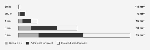 Figure 2. Exhibit A drawn to scale (bar length = installed cross-section). The load is the same 200 W in every row; only the distance changes. Beyond a few hundred meters, rule 3 accounts for more copper than rules 1 and 2 combined, and rounding up to a standard size adds the rest.
Reading the result:
- At 50 m, rules 1 and 2 need very little copper and rule 3 adds nothing. The smallest standard size, 1.5 mm², is sufficient.
- At 500 m, rule 3 requires more than twice the copper of rules 1 and 2 combined.
- From 1 km to 5 km, rule 3 dominates further, and the installed size grows to 16, 50 and 95 mm² for an unchanged 200 W load.
Over long distances, the AC conductor is sized by fault disconnection rather than by the power the device needs. A 200 W device 1 km away requires a 16 mm² AC conductor. That copper, and the transport, trenching and handling that come with a cable of that size, make up much of the infrastructure cost discussed in section 11.
The same calculation at 2 km gives a practical minimum of 35 mm². For comparison, an InOne hybrid cable uses conductors several times smaller over the same distances. The actual InOne conductor size for a given layout and load is calculated in the InOne design tool (section 9).
Note on breaker choice: Exhibit A assumes a B10 breaker. A smaller breaker rating lowers the fault current needed for fast disconnection and so reduces the extra copper required by rule 3, but it does not remove the requirement. Voltage drop (rule 2) still applies, and the breaker must also handle the inrush and future load of the connected equipment. Actual sizing depends on the specific design and local regulations.
6. The six InOne design decisionsInOne was designed around six decisions, each aimed at a cause of oversized AC cables or at a known weakness of conventional field power.
Decision 1: DC instead of AC, at 110 V (extra-low voltage)
DC on its own does not solve the problem, but it enables the other decisions. InOne operates at 110 V DC, which is within the extra-low voltage (ELV) range of up to 120 V DC. The HDN output can be adjusted up to 120 V DC; InOne networks are configured and recommended at 110 V DC. The DC network is floating (not earthed). Basic protection against direct contact is provided by the cable insulation and the IP65 HAN enclosures.
Because InOne operates at extra-low voltage, in many countries the DC network can be installed without a licensed electrician. The 230 V AC connection to the HDN must still be made by a qualified electrician. Local regulations should be checked for each project.
Decision 2: one hybrid micro cable for power and fiber
Instead of a power cable and a separate fiber cable, InOne combines copper conductors and optical fibers in one hybrid cable. The design target is a micro cable with an outer diameter of 6–12 mm.
Decision 3: purpose-built electronic fuses instead of MCBs
A micro cable is only possible if the reason for oversizing is removed. An MCB needs a high fault current to trip quickly, which is why AC rule 3 drives the conductor size. InOne instead uses Hexatronic's purpose-built electronic fuses. An electronic fuse measures the current electronically and disconnects within milliseconds when the current exceeds a programmable or selectable threshold. It does not depend on a high fault current, so the additional copper required by rule 3, the largest contributor in Exhibit A, is not needed.
Decision 4: allow up to 50% voltage drop instead of 5%
AC practice limits the voltage drop to about 5%. InOne allows the voltage to fall by up to 50% along a line, from 110 V to 55 V DC, because every HAN regulates its input to a stable output voltage (section 7). This allows much smaller conductors.
The 50% limit is a stability limit. A regulated device draws constant power, so its current rises as its input voltage falls. Below about half the source voltage, a further increase in current reduces the delivered power, and the voltage collapses quickly. 50% is the point of maximum power transfer. InOne networks are therefore never designed to go below 55 V DC at any HAN.
Decision 5: any topology, simple deployment, no technology risk, observable
The system must support point-to-point, daisy chain, tree/fan-out and ring topologies. It must be easy to deploy, use proven technology, and be observable: HAN sensors report voltage, current and other values to any management system for fault prediction, analysis and troubleshooting (section 10).
Decision 6: built for high availability
Availability is provided by redundant power supplies in the HDN, redundant cable routes using ring topology, and a centralized UPS at the head end instead of many UPS units distributed in the field.
| Constraint in a 230 V AC design | InOne decision |
|---|---|
| Low-voltage AC installation requires an electrician | 110 V DC, extra-low voltage |
| Separate power and fiber cables | One hybrid micro cable, 6–12 mm |
| Rule 3: MCB disconnection time forces thick copper | Electronic fuses, disconnection in milliseconds |
| Rule 2: about 5% voltage-drop limit | Up to 50% drop, regulated at every HAN |
| Fixed, hard-to-extend circuits | Any topology, sensors at every node |
| Distributed UPS, single points of failure | Redundant supplies, ring routes, central UPS |
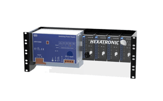
The InOne system consists of three physical parts: the Hybrid Distribution Node (HDN) at the head end, the hybrid micro cable in the field, and the Hybrid Access Node (HAN) at each device location.
1 · HDN
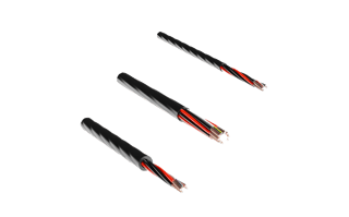
2 · Hybrid micro cable
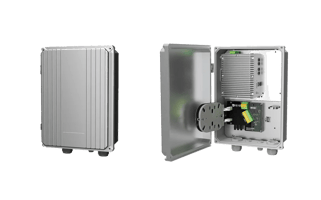
3 · HAN
7.1 HDN – Hybrid Distribution Node
The HDN is installed at the head end, typically in an equipment room or cabinet. It combines three functions:
- Rectifier: converts 230 V AC to 110 V DC.
- H-ODF (hybrid optical distribution frame): combines the 110 V DC with the optical fibers into the outgoing hybrid cables.
- Current limiter / electronic fuse: protects each outgoing line (decision 3 and section 8).
7.2 Hybrid micro cable
One cable carries copper conductors for DC power and optical fibers. Cable types are available for different installation methods:
- Blowable: installed by blowing into ducts, the same ducts used for standard fiber optic cable.
- Aerial: for overhead installation between poles.
- Direct buried: laid directly in the ground without ducts.
- Tactical: rugged cable for temporary or rapid deployment.
- Fire-retardant, CPR-rated: for indoor and building installations, available in CPR class D (Dca) and class C (Cca) under EN 50575.
7.3 HAN – Hybrid Access Node
The HAN is installed at the device location, for example on a pole, a wall or in a field cabinet. It terminates the hybrid cable and delivers power and data to the devices.
Enclosure and cooling. The HAN is an IP65-rated cast aluminum enclosure. The enclosure acts as the heat sink for the heat-generating components inside it, the voltage regulator and the industrial switch. In steady state the HAN is passively cooled: no fans, no active cooling and no air conditioning.
Fiber handling.
- The hybrid cable enters the HAN and the power conductors are separated from the fibers.
- The fibers are spliced in the fiber tray.
- The fibers used at this location are routed to the industrial switch.
- The remaining fibers are spliced through to continue to the next HAN.
Voltage regulation. The input voltage at a HAN lies between 110 V and 55 V DC, depending on its position in the network. The regulator works as both a step-down and a step-up converter and outputs a stable 48 V DC, the standard telecom voltage. Some industrial switches require more than 48 V; a mechanical switch inside the HAN sets the regulator to boost mode, which gives about 53 V DC. The regulator also isolates the devices from load fluctuations elsewhere in the network.
Industrial switch and PoE. The regulated output feeds an industrial Ethernet switch. Hexatronic does not supply the switch; the customer chooses the brand according to their IT strategy. Cameras, radars, sensors and other devices connect to the switch and receive power and data over Power over Ethernet (PoE).
7.4 The complete power and data chain
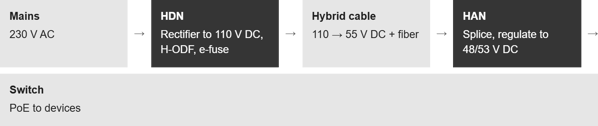 Figure 4. Power and data path from the mains connection at the head end to a PoE device in the field.
This chain lets devices several kilometers from the head end be served by one micro cable, with standard PoE at the edge.
8. Topologies, redundancy and fault behaviorOne HDN (input 230 V AC, output 110 V DC) can feed several topologies at the same time over the same hybrid cable type:
- Point-to-point: one HAN per line.
- Daisy chain: HANs connected in series along one route, for example along a road, fence or pipeline.
- Tree / fan-out: branches split from a main line to reach devices in different directions.
- Ring: the route is closed back to the HDN, so every HAN can be fed from both directions.
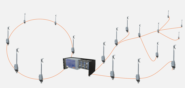 Figure 5. One HDN feeding a redundant ring (left) and daisy-chain and tree/fan-out branches (right) over a single hybrid cable type.
Ring redundancy
In a ring, a single cable cut anywhere on the route does not disconnect any HAN: power and fiber continue to reach every node from the other direction. A ring is the appropriate choice where a cable cut must not cause downtime, such as perimeter security or critical CCTV.
Fault behavior of the electronic fuse
When a short circuit occurs on a line:
- The electronic fuse detects the overcurrent and cuts the voltage within milliseconds.
- It then periodically retries, briefly applying voltage to check whether the fault is still present.
- If the fault clears, for example when a temporary short opens, the electronic fuse restores the voltage automatically.
- If the fault is permanent, the voltage stays off until the fault is repaired.
In Hexatronic's lab tests, the interruption caused by a temporary fault lasted 2–400 ms. Because the electronic fuse limits the current and reacts within milliseconds, a fault does not need, and does not receive, the sustained high current that an MCB requires to trip.
9. Voltage profile, efficiency and the InOne design toolAlong a daisy chain, the voltage falls at each section because of the resistance of the cable. The design rule is that no HAN may receive less than 55 V DC, half of the 110 V source; once a line reaches that limit, no further distance or nodes are added. Figure 6 and the table below show a real example from the InOne design tool.
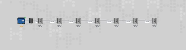 Figure 6. Daisy chain in the InOne design tool: one HDN feeding seven HANs at 200 m spacing (1.4 km in total). Loads per node: 90, 90, 90, 90, 70, 90 and 70 W (590 W in total). Every HAN outputs a regulated 48 V (or 53 V) DC regardless of its input voltage.
| Node | Distance from HDN | Load | Input voltage (DC) | Current in section | Drop in section |
|---|---|---|---|---|---|
| HDN | 0 m | 990 W (output) | 110 V | – | – |
| Node 1 | 200 m | 90 W | 98 V | 9.02 A | 12 V |
| Node 2 | 400 m | 90 W | 88 V | 7.97 A | 10 V |
| Node 3 | 600 m | 90 W | 79 V | 6.80 A | 9 V |
| Node 4 | 800 m | 90 W | 72 V | 5.51 A | 7 V |
| Node 5 | 1,000 m | 70 W | 67 V | 4.09 A | 5 V |
| Node 6 | 1,200 m | 90 W | 64 V | 2.90 A | 3 V |
| Node 7 | 1,400 m | 70 W | 62 V | 1.29 A | 2 V |
Two properties of this example are typical. First, the voltage drop per section decreases along the line, from 12 V in the first section to 2 V in the last, because each HAN takes its share of the current and less current flows in the remaining cable. The current falls from 9.02 A in the first section to 1.29 A in the last, which is why the drop falls with it. Second, the last node receives 62 V, above the 55 V limit, so this line is within the design rules. Each HAN regulates its input, whether 98 V or 62 V, to the same 48 V (or 53 V) output.
Voltage drop and power loss. Voltage drop in a cable corresponds to power loss: the loss in a section equals the current multiplied by the voltage drop across it, dissipated as heat in the copper. Every device still receives its full power, because the HAN regulator draws slightly more current at lower input voltage and delivers a constant output. The 50% figure is the voltage limit at the end of a line, not the overall loss. Loads are tapped off along the chain, so the current and the losses decrease toward the far end, and total system efficiency is higher than the end-of-line voltage suggests.
The InOne design tool
Hexatronic provides an online design tool for InOne networks at www.inone-design.com. The user enters the network layout and devices, and the tool calculates:
- the voltage at every HAN;
- the current in each cable section;
- the resistance of each cable section.
The tool flags a design in red when:
- the voltage at any HAN falls below 55 V DC, or
- the total load exceeds the capacity of the power supply unit (PSU) in the HDN.
Integrators and consultants should run each project through the design tool before quoting. It shows how far each line can extend and how many HANs and devices it can carry, and it gives the cable losses for the specific design.
10. Monitoring: InOne AMS (Alarm & Monitoring System)The HAN carries sensors that report the state of the physical layer at every node. The data can be read by any management system, including a network management system (NMS), a physical security information management system (PSIM) or a video management system (VMS), over SNMP or Modbus over IP. Hexatronic continues to add sensor types.
| Sensor | Information provided |
|---|---|
| Magnetic door sensor | Cabinet open or closed, with time stamps |
| Seismic tamper sensor | Alarm when the cabinet is being tampered with |
| Voltage and current card (optional) | Incoming line voltage, regulated output voltage, current in and current out |
| Temperature and humidity sensor | Conditions inside the enclosure |
Diagnostics from voltage and current
- Power or device fault. If a camera or switch stops responding, the HAN voltage shows immediately whether the cause is a power problem or a device problem.
- Cable damage or unauthorized tapping. In a daisy chain, the current out of one HAN (for example HAN 4) must equal the current into the next HAN (HAN 5). A difference indicates either unauthorized power tapping or damage to the cable between the two nodes.
- Locating a cable cut. After a cut, the last HAN that still reports voltage identifies the section in which the cut lies.
Why physical-layer alarms matter
Most monitoring systems already provide alarms and analytics for the higher layers: layer 2 and layer 3 networking and the devices themselves. InOne AMS adds alarms from the physical layer, the power and the cable. These alarms are often the most critical, because a fault in the physical infrastructure affects every device behind it.
In security applications, a cable cut can indicate intrusion or sabotage. A cable-cut alarm can therefore be handled as a security event: guards are dispatched before technicians.
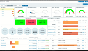
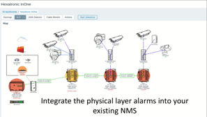 Figure 7. InOne AMS: map view with node and camera alarms (left); HAN dashboard with voltage, current, temperature and alarm history (right).
Current situation
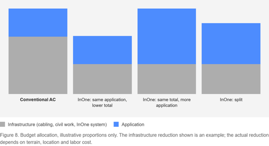
In a typical project powered by AC, roughly two thirds of the budget goes to infrastructure and one third to the application. Infrastructure includes:
- power cables and fiber optic cables, and everything associated with the power cable;
- transport and handling, which are expensive because AC cables over long distances are large and heavy;
- civil work. In many countries, power cables and fiber optic cables may not share a trench, which leads to separate or deeper trenching, surface reinstatement, removal and disposal of excavated material, and disruption to existing infrastructure, traffic and the public.
The application is what the customer actually wants to buy. In a CCTV project, that is cameras, radars, sensors and software.
The two-thirds figure is an average based on customer feedback from infrastructure projects. It varies mainly with the cost of civil work. Inside city limits, excavation is very expensive and infrastructure can be well over two thirds of the budget. In open terrain, for example plowing into sand around a remote facility or into forest ground, civil work costs much less. The cost is also driven by terrain (rock or soft ground) and local labor rates.
Target situation
Every customer wants to reduce infrastructure cost, provided that the alternative infrastructure performs at least as well as the conventional one. InOne reduces civil work and cabling cost. The cost of the InOne system has to be added, but the total infrastructure cost is lower than in the conventional design, so the same application can be delivered for less. The size of the saving depends on how expensive the infrastructure is in the specific project: the more expensive the civil work, the larger the saving.
How the saving can be used
The customer decides how to use the reduction in infrastructure cost:
- Lower the total: deploy the same application at a lower total project cost.
- Invest more in the application: keep the original budget and spend the difference on more or better devices, wider coverage or better software. This applies to security systems, 5G small cells and microcells, or other IoT applications.
- Combine both: keep part of the saving and reinvest the rest.
Infrastructure is the baseline a project must have; the application is the business objective. Lower infrastructure cost lets the customer choose the balance between the two.
12. Frequently asked questionsCan an RCD solve the AC cable-size problem?
An RCD (residual current device) can help disconnect earth faults quickly, but it does not remove the other constraints of a 230 V AC design. Overcurrent and short-circuit protection is still required, the conductor must still be sized for voltage drop over long distances, and the installation must still be carried out by an electrician. RCD use should be checked against local regulations and the specific network design. An RCD is not applicable on the InOne DC side, because the DC network is floating and has no earth reference.
Why 110 V DC and not 48 V DC on the cable?
For a given power, a higher voltage means a lower current and therefore lower losses and a smaller conductor. 110 V DC remains within the extra-low voltage range (up to 120 V DC). The HAN converts it to 48 V or 53 V DC locally for the switch and PoE devices.
Does a 50% voltage drop mean 50% of the energy is lost?
No. 50% is the lowest permitted input voltage at the last HAN of a line, not the overall loss. Because loads are distributed along the line, current and losses decrease toward the far end. The design tool calculates the actual losses for each design.
Does an InOne installation need a licensed electrician?
In many countries the extra-low-voltage DC network can be installed without a licensed electrician. The 230 V AC supply to the HDN must be connected by a qualified electrician. Local regulations apply.
Can InOne share ducts with fiber?
The blowable hybrid micro cable is installed in the same ducts used for standard fiber optic cable.
Which industrial switch is used in the HAN?
The customer selects the switch according to their IT standard. Hexatronic does not supply it. The HAN provides 48 V DC, or about 53 V DC in boost mode, and the fiber connection.
What happens if the cable is cut?
In a ring, all HANs remain powered and connected from the other direction. In all topologies, the AMS voltage readings show the last HAN with voltage, which identifies the affected section. In security applications a cut can be treated as an intrusion alarm.
13. GlossaryAMSAlarm & Monitoring System; InOne's physical-layer monitoring of HAN sensors.CPRConstruction Products Regulation (EU); cables are classified for reaction to fire under EN 50575 (for example Cca, Dca).ELVExtra-low voltage; up to 120 V ripple-free DC or 50 V AC.Electronic fuseElectronic current limiter that disconnects within milliseconds at a set current threshold, independent of fault-current magnitude.HANHybrid Access Node; IP65 field enclosure that terminates the hybrid cable, regulates the voltage and houses the industrial switch.HDNHybrid Distribution Node; head-end unit with rectifier (230 V AC to 110 V DC), H-ODF and electronic fuses.H-ODFHybrid optical distribution frame; combines DC power and fibers into the hybrid cable.MCBMiniature circuit breaker; thermal-magnetic protective device used in AC installations.PoEPower over Ethernet; power and data to a device over one Ethernet cable.PSIM / VMS / NMSPhysical security information management / video management system / network management system.PTZPan-tilt-zoom camera.TN-SEarthing system with separate neutral and protective earth conductors throughout.ZsEarth fault-loop impedance; determines the fault current available to trip a protective device.Scope: AC figures refer to low-voltage 230 V installations under HD 60364 / IEC 60364 principles. National regulations differ in detail; verify against local rules for each project. InOne conductor sizes for a specific design are calculated in the InOne design tool.
Hexatronic Powered Fiber · hexatronic.com/en/powered-fiber · inone-design.com · Last updated October 2026