The InOne HDN is supplied in two variations Active and Passive (click here to know the difference between Active and Passive InOne Systems)
The InOne HDN (Hybrid Distribution Node) consist PSUs (AC/DC rectifiers), a H-ODF (Hybrid-Optical Distribution Frame) and a 4U 19" Din Rail Rack
Product Links
- H-ODF (Hybrid-Optical Distribution Frame)
- PSUs ( AC/DC rectifiers and redundancy controller)
- 4U 19" Din-Rail Rack
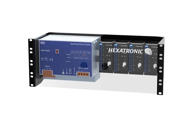
The 4U Rack installation
The 4U rack can be installed in a standard 10" rack. The placement in the rack should facilitate the routing of the InOne hybrid cables that are quite stiff due to it's strengthing member.
Is is easier to install the PSU in the 4U rack prior to install the 4U rack in the 19" cabinet.
The H-ODF Installation
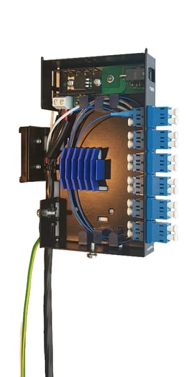
The Hybrid ODF is designed to be mounted on a DIN rail in suitable cabinet. Preferably close to the DC power source of 110 VDC.
Included parts
• Hybrid ODF
• Cable ties
• Plastic tube
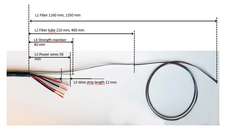
Prepare the Hybrid Micro cable
Open and prepare the Hybrid Micro Cable according to instruction 1553-TOL40790+
Cutting lengths as below figure:
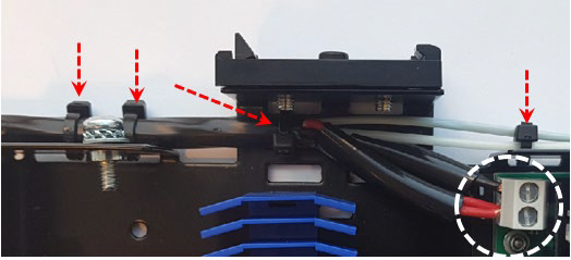
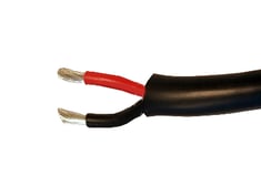
Connect power wires
Twist the two red stripped wires together and the two black stripped wires together. Cut the wires to a stripping length of 8mm. Put the black plastic tube above the wires (Electrical protection)
Mount the power wires to connecting block,
Red wires to + and black wires to -
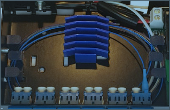
Mount the cable to ODF with enclosed cable ties at positions marked in photo below
Splicing fiber
Splice the fibers of hybrid micro cable to suitable number of fiber pigtails.
Place the splice in splice holder and wind overlengths of fiber according to picture below
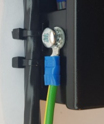
Grounding
Connect the Hybrid ODF to site earth
Connecting the ODF to power source.
Caution! The Hybrid ODF shall only be powered with a voltage less than 120 Vdc isolated from power network and fulfilling the requirements of ripple according to class ES 2 in IEC 62368-1.
Suitable power source is HBMR136200+
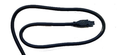
Connect power cable to power source
Connect the hybrid ODF to power source with the enclosed power cable
• Red conductor to +
• Black conductor to –
Connect power cable to Hybrid ODF
Before connecting power to ODF ensure all terminations is finished in all connected terminations attached to the hybrid cable.
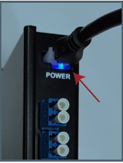
A blue light at power connector indicate correct wiring and power source is working.
Polarity protection in ODF will make the power source to shut down if unit is not connected with correct polarity.
Finally, Connect Optical patch cords to your optical network
The PSU ( AC / DC rectifiers ) Installation
For the Active HDN you can get PSUs in either 480 W or 1000 W output power
Installation Steps:-
- Make sure that all InOne cables are fully terminated on all HANs and all device wiring is terminated prior to commencing in installing the PSU
- You only need on PSU for non redundant installation, if redundancy is needed please check the section below. (PSU Redundancy)
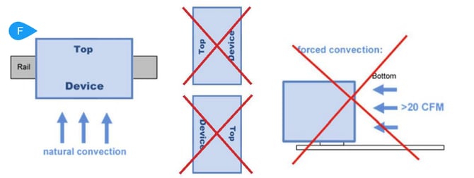
- Install the PSU on the Din-Rail in the proper orientation (ref F)
- Use a cabinate with minimum IP20. To allow adequate convection, a free air space of 50mm (top/bottom) and 10mm (sidewalls) is required
- All components of the HDN including the PSU is for indoor use with proper air circulation. Approved outdoor cabinets only can be used for outdoor installation.
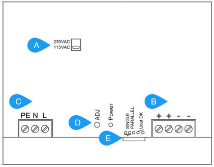
- Make sure the input AC Voltage is set to your country's AC Power level ( PSUs are shipped out with 230 VAC, but important that you double check) (ref A)
- Connect the DC Voltage output (Typically adjusted to 110 VDC) to the H-ODF. Some H-ODFs are supplied with DC cable that you can use, otherwise you need to supply your own. (ref B)
- Use DC rated cable. Its recommended to use red and black wires to remain consistent with the InOne hybrid cable wiring if you using other colors make sure to remain consistent to make sure wires are connected to the correct polarity.
- Wire diameter depends on the load but 1.5mm2 is sufficient.
- Connect AC Power cable (not supplied) for the AC input (ref C) Follow the safety standards in your country.
- AC power feed should be connected to 16A circuit breaker with C characteristic
- Before you turn on the AC Power check the following
- All input and output connections are done according to the product labels
- The H-ODF is fully connected and all output cables are fully terminated on HANs in that cable segment.
- Make sure all devices Like Switches or Media Convertors in all the HAN are connected and no open wire are left unterminated.
- Make sure that the polarity on PSU, H-ODF, HANs and Devices are consistent
- Make sure all HAN door are properly closed
- Inform Other installers or any other concerned persons that the power will be turned on
- Turn On the AC Power and immediately check the DC output with a DC voltmeter The voltage should measure around 110VDC
- To adjust the output voltage use the potentiometer (ref D) . See instructions below (Output Voltage Adjustment)
- Connect the relay contact (ref E) if you need a DC-OK alarm. The DC ok relay indicates if the output voltage is low and if the AC voltage is low
- If there is no DC output voltage
- disconnect the load and check again
- A clicking sound from the PSU indicates a short circuit on the output
PSU Redundancy
In high availability applications or if breakdowns cost a lot of money and a service call is expensive, it is advisable to operate the power supply redundantly.
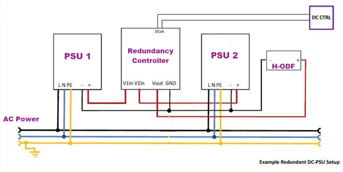
For redundancy you will need two identical PSUs and one redundancy controller. Please note that the total power capacity is equal the total power capacity of one of the PSUs only
Installation steps
- Follow all the guidelines in installing the PSUs above
- Connect the wiring between the two PSUs and the redundancy controller as above
- Adjust the output voltage of each PSU so both PSU are at the same voltage level as follows
- When everything is connected as above and the power is on
- Use a voltmeter at the redundancy controller and measure V1in and V2in.
- Adjust the Voltage at the PSUs as described above to make both voltage levels as equal as possible (within 1 volt)
- To adjust the output voltage use the potentiometer (ref D) . See instructions below
DC output Voltage adjustment
- connect a DC voltmeter to the PSU output that you want to adjust.
- Keep watching the voltmeter when turning the "ADJ" screw
- Adjust the potentiometer labeled "ADJ" Infront of the PSU (ref D) above
- Use insulated fine screwdriver with 2mm slotted head (flat head) and 22mm long shaft. The potentiometer is around 20mm deep. See picture below
- This is 1-turn potentiometer (360 degrees) only use fine delicate movements.
- Practically you only need to turn it 1/10 of a turn in each direction to calibrate both PSUs to the same voltage level
- Extra tip : Some PSUs will have a "hiss" sound when uncalibrated which will disappear when both PSUs are at the same level