![Hexatronic_Group_avatar_RGB.png]](https://knowledge.hexatronic.com/hs-fs/hubfs/Hexatronic_Group_avatar_RGB.png?width=40&height=40&name=Hexatronic_Group_avatar_RGB.png)
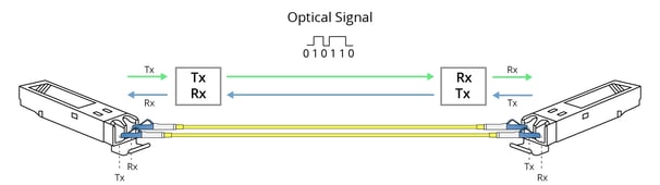
The basic rule when connecting SFPs in a point-to-point topology is to connect Rx to Tx and connect Tx to Rx as shown in the diagram before. Fiber technicians should keep an accurate record of all fiber connections and label all pigtails appropriately.
In this article, we will show an example of Fiber Connection Diagrams for 2 topologies.
The Daisy-Chain Topology
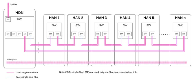
A Daisy chain is a common practice for connecting devices when devices are connected serially and the main cable passes through all the devices.
The main advantages of the Daisy Chain are
- In the InOne daisy-chain arrangement shown below, only four fiber cores are required regardless of the number of HANs
- It utilizes only 2 ports on the aggregation/edge Switch
- If the switch or media convertor in the HAN supports RSTP/MSTP, ERPS/G.8032 or similar you can acheive ring failure redundancy. The loop redudancy can work only if its specifications explicitly support switching and the required redundancy protocol.
The Star Topology
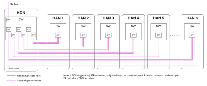
An alternative to daisy chain topology is the star topology as shown in the diagram below
The advantage of the star fiber topology that each SW or MC has its dedicated fiber any failure in any number of SW/MC will keep the fault localized and will not affect other SW/MC
This disadvantage is that it has a higher use of fiber cores, you can partially midgait that by using BiDi SFP with one fiber core per SFP, but in both case utilises more SFP port at the Swtich in the HDN