![Hexatronic_Group_avatar_RGB.png]](https://knowledge.hexatronic.com/hs-fs/hubfs/Hexatronic_Group_avatar_RGB.png?width=40&height=40&name=Hexatronic_Group_avatar_RGB.png)
InOne Hybrid Cable Selection Guide
Selecting the correct InOne Hybrid Cable depends primarily on the installation environment and the required copper conductor size. The selection matrix below provides a quick way to identify the recommended cable for your application.
Start by selecting the installation method on the left, then choose the required conductor size across the top. The intersection identifies the recommended cable part number. If no cable is available for a particular combination, the cell is marked ×.
Once you have identified the appropriate cable, continue to the detailed portfolio below for the full technical specifications, construction details, fiber options, conductor information, and downloadable datasheets.
| AWG18/4F | 1.5mm2/12F | 3mm2/24F | 6mm2/12-24F | 10mm2/24F | |
| Blowable Ducted | x | TOL4079028/12 | TOL4079029/24 | ||
| Direct Buried | x | x | x | TOL4079043/12 | x |
| Non-Blowable Ducted | x | x | x | x | TOL4079038/24 |
| Aireal | x | x | x | TOL4079037/48C | x |
| CPR Class C | x | x | x | Coming Soon | x |
| CPR Class D | x | TOL4079030/12 | TOL4079031/24 | x | x |
| Tactical | HRPM254213/XM | x | x | x | x |
- AWG 18 / 4F – 18 AWG copper conductors with 4 optical fibers.
- 1.5 mm² / 12F – 1.5 mm² copper conductors with 12 optical fibers.
- 3 mm² / 24F – 3 mm² copper conductors with 24 optical fibers.
- 6 mm² / 12–24F – 6 mm² copper conductors available with either 12 or 24 optical fibers, depending on the cable type.
- 10 mm² / 24F – 10 mm² copper conductors with 24 optical fibers.
- × indicates that no standard cable is available for that combination.
- Often the InOne Hybrid cables come in 4 or 8 copper wire in one cable despite that in most applications you need only 2 wires for DC. The reason for that is keep the whole cable round to insure the cable is blowable in micro ducts. see figure 1 below
- The copper wires insulation is colored red or black. During installation all reds must be joined together and all blacks must be joined together at both ends of every cable segment. This will effectively provide 2 copper conductor with the sum of the area of the joined wires. For an example if you use the cable TOL4079029/24 which has 4x1.5mm2 copper cables 2 black and 2 red (Figure 1 below) and you join similar color copper conductors at both ends you get an effective copper of 2 x 3mm2 and this measurement should be the base of your power calculations.
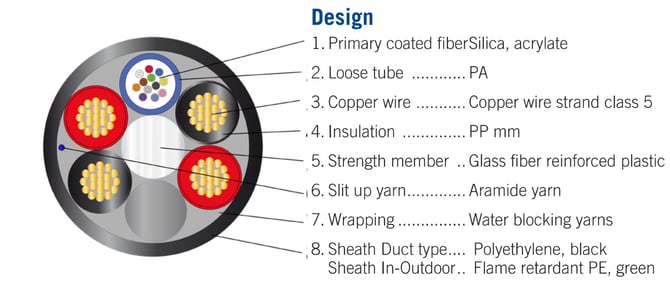
Figure 1 - InOne Hybrid Cable Cross Section
Notes regarding AWG (American Wire Gauge)
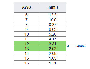
Each AWG step changes the diameter in certain ratio, those steps do not convert to the metric mm2 area in whole numbers (integers) therefore there is no accurate conversation between AWG and mm2 without using decimals.
Many internet resources round down the result which result in an inaccurate conversation. For best and accurate result to calculate the power budget of any cable over a certain distance and load refer the InOne Design Tool or the table at the end of this article below.
If we use the same example of the cable TOL4079029/24 which has 4x1.5mm2 i.e. 2 x 3mm2 this will fall between AWG 13 and AWG 12 as in the table below (wiki article)
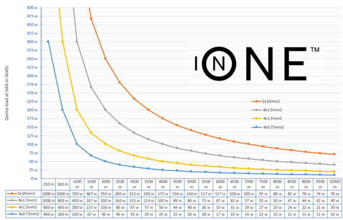
InOne Load vs Distance chart and table
The below chart is for point to point quick reference guide for more elaborate design refer the InOne Design tool at www.inone-design.com and read the InOne Design Tool guide